How to Define Your Board Shape and Size
Estimated reading time: 5 minutes
Every board has an outline — the edge the factory cuts the PCB to. In Protoboard Designer your board is always a solid shape with a closed edge: a new project starts as a rectangle, so there's nothing to "remember to add" and no way to leave the outline open or broken. What you control is its size and, when you want, its shape. This guide shows how.
You don't draw the outline as copper — it's the board's own shape, which is always there. You edit it with the Machining tool (in Outline mode). The separate Milling layer is for internal cut-outs and slots inside that edge. See Understanding PCB Layers.
Set the size
The fastest way to size a board is by its dimensions:
- Open the Board Settings tool from the left toolbar.
- Go to the Board Dimensions section.
- Enter the width and height (in your current units — switch units under Board Settings → Unit System).
A rectangular outline is created for you at that size. For many projects you're done here.
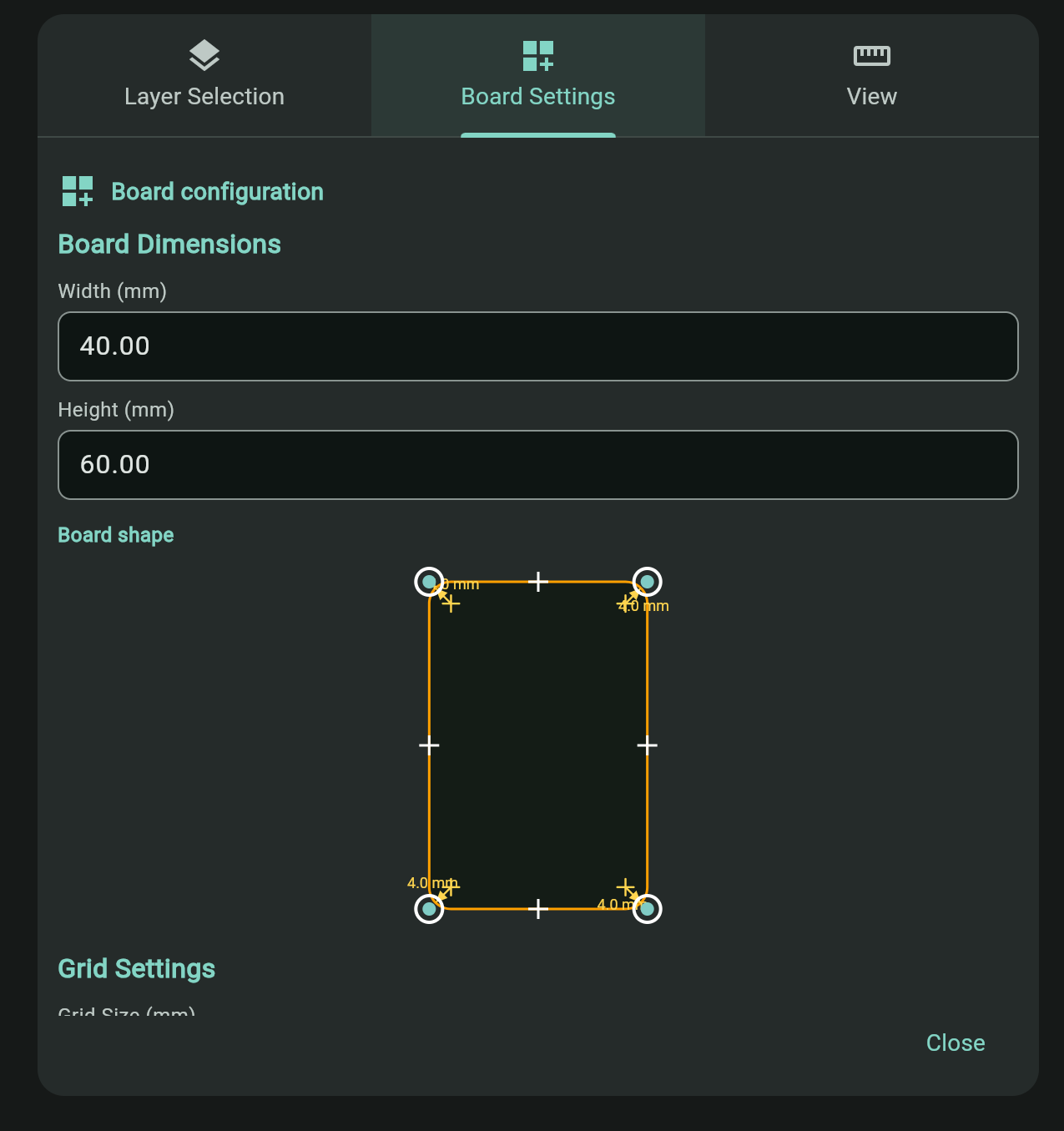
Pick a size a bit larger than your parts need so routing stays easy. You can change the dimensions later as the design grows.
Shape it: corners, edges, and rounded corners
Need something other than a plain rectangle? Use the Machining tool to edit the outline directly on the canvas:
- Drag a corner to move it and reshape the board.
- Tap an edge midpoint to add a new corner there — repeat to build an L-shape, a notch, or a polygon.
- Select a corner to set its radius individually, for rounded corners.
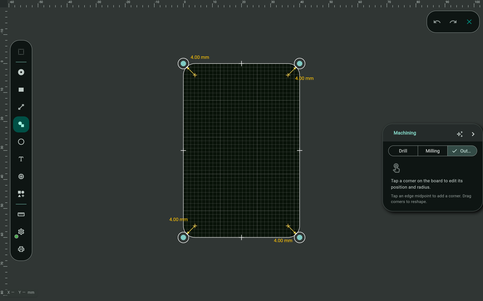
The board is always a single, closed shape — Protoboard Designer keeps it valid for you, so you never have to worry about gaps or an unclosed loop. The only edit it won't allow is one where the edge would cross itself: if dragging a corner would make the outline self-intersect, the editor rejects the move.
Keep everything inside
The factory trims the board at the outline, so anything sticking out past the edge is lost — or gets your order rejected. Leave a small margin (a millimetre or two) between your copper and the board edge.
Protoboard Designer's DRC has an Elements outside board outline check that flags any pad, track, via, or hole that pokes past the edge. Run it before exporting — see Check Your Design with DRC.
Quick checklist
- Set width/height in Board Settings → Board Dimensions.
- Reshape with the Machining tool (drag corners, tap edges to add corners, set corner radius).
- The edge stays closed and valid automatically — just avoid self-crossing shapes.
- All copper sits inside the edge with a small margin.
Troubleshooting
My manufacturer says there's no board outline
Protoboard Designer always exports the board outline (it's generated from your board shape), so this is rare. If it happens, confirm the outline/board layer was included when you export Gerbers, and that any custom shape you made isn't self-intersecting.
Part of my board got cut off
Something extended past the outline. Run the DRC's Elements outside board outline check, then move the offending elements inside the edge (or enlarge the board).